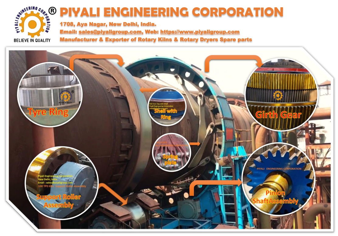
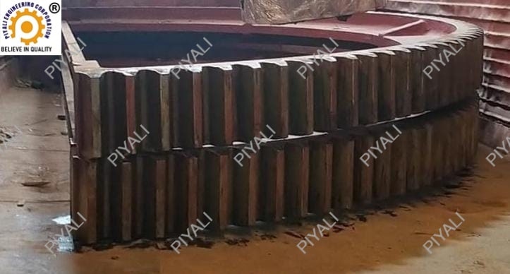
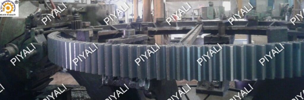
100 TPD Kiln Girth Gear in Sponge Iron Plant
The 100 TPD kiln girth gear is an important component in the rotary kiln system of a sponge iron plant. In this product specification, the module is a millimeter-based measurement of the size of the gear teeth. The kiln’s capacity is the quantity of material they can handle in a single day. The diameter is a key factor that affects the size and power of the entire structure.
PRODUCT SPECIFICATIONS: 100 TPD KILN GIRTH GEAR
- MODULES – 40 Module
- CAPACITY – 100 TPD Rotary Kilns for Sponge Iron Steel Plant
- CERTIFICATION – ISO9001
- NO. OF TEETH – 112 Nos.
- DIAMETER – 4616 MM (Corrected)
- MATERIAL GRADE – CAST STEEL IS 2708 Grade 2/3, IS 2644 Grade CS 700, GS34CrMo4
- DESIGN – AS PER CUSTOMER PROVIDED (POPURI / IPS / ITC / MEC / LURGI etc.)
WHY CHOOSE PIYALI?
- PIYALI GROUP is a manufacturer, supplier, and exporter of high-quality kiln girth gears.
- PIYALI GROUP offers excellent supply and export services that are beneficial for businesses seeking to purchase kiln spares from a reputable supplier.
- To produce high-quality girth gears with a high accuracy and precision, PIYALI GROUP employs more experienced workers and engineers.
- PIYALI GROUP conducts quality control procedures to ensure that the products meet or exceed industry standards.
Piyali Group has a team of experienced engineers and technicians to meet the specific needs of their customers. We, Piyali Engineering Corporation, manufacture and export products to the various states of India including Maharashtra, Karnataka, Andhra Pradesh, West Bengal, Odisha, Bihar, Jharkhand, Chhattisgarh, Gujrat, Tamil Nadu, Meghalaya, Tripura, Himachal Pradesh, Haryana, Telangana and others. The company has a modern manufacturing facility in Ghaziabad, Uttar Pradesh, India, which is equipped with the latest machinery and technology to produce high quality products. The company has a global presence and exports its products to other countries. Some international customers are located in Egypt, Sweden, Jordan, Srilnaka, Canada and the United States.
GEAR MANUFACTURING PROCESS:
With 30 years of experience, PIYALI GROUP is an expert in the manufacturing and processing of rotary kiln parts. The production of girth gear involves a number of steps from the raw material’s transformation to the finished product. The basic steps in processing 100 TDP kiln girth gears are as follows:

STEP 1: Casting simulation
Piyali Group is a leading manufacturer of industrial equipment in India, including girth gears, kiln shells, and others.
The casting simulation process used by Piyali Group includes the following steps:
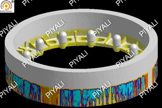
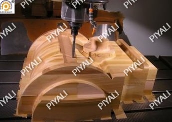
- CAD model design: The first step is to create a 3D CAD model of the component. For designing the model, we use special software which includes essential features such as sprue channels, feeders and gating systems.
- Meshing: Meshing is the process to divide the CAD model into small finite elements using specialized software to analyze individually.
- Material properties: Material properties such as thermal conductivity, specific heat, and viscosity assigns to each element for further processing.
- Boundary conditions: Boundary conditions such as temperature and velocity are specified for each element. This allows engineers to simulate the behavior of molten metal into the mold.
- Simulation: The simulation uses the special software, which solves the mathematical equations that govern the behavior of the molten metal. The software predicts various parameters such as temperature distribution, flow velocity, and solidification time.
- Analysis: Analysis includes simulation’s outcome to identify potential defects such as shrinkage, porosity, and hot spots. This allows engineers to modify the mold design to eliminate or minimize these defects.
- Optimization: Based on the analysis, engineers can optimize the casting process by adjusting the gating system, mold design, and material properties. This helps to ensure that the casting process produces high-quality components that meet the required specifications.
Piyali Group uses casting simulation to ensure that its cast components meet the highest quality standards. Piyali Group is a leading manufacturer of industrial equipment and machinery with experienced and trained staff to deliver high-quality components to its customers.
STEP 2: Casting
Casting is one of the manufacturing methods used for producing gears. It entails pouring molten metal into a mold in order to produce the desired shape and size of the gear. Sand casting is a preferred manufacturing process for girth gears. The procedure includes the use of a sand mold to shape the molten metal into the desired form. The sand mold is packing sand around a pattern that represents the finished gear shape.
CASTING PROCESS:
In the casting manufacturing process, a liquid material is pour into a mold, which contains an internal cavity of the desire shape. After this, it allow it to cool down.
- The casting process begins with the creation of a pattern for a mold. In order to make a mold, place a design in the sand.
- Pattern uses the wood, plastic, or metal material to form the same form and size as the gear’s design.
- Pour molten metal into the mold cavity.
The stages in the sand casting process for manufacturing gear are as follows:
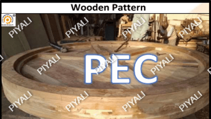
WOODEN PATTERN
This is the first step in the procedure is to create a wooden pattern that is an exact copy of the gear.
The steps in the wooden pattern inspection are as follows:
- Dimensional Inspection: Dimensional inspection allows to check the pattern to ensure that it is of the correct size and shape for the casting. Dimensional inspection uses various precision instruments such as calipers, micrometers, and gauges for measurements.
- Material Inspection: The material inspection is necessary to ensure that it is of high quality and complies with the casting process’s requirements.
- Surface quality: The pattern’s surface must be flawless and free of flaws like knots, fissures, or rough patches.
- Alignment: To ensure that the pattern does not shift during the casting process, proper alignment is necessary.
- Inspection of the pattern assembly: In this type of inspection, the pieces should fit together correctly to make sure that there are no flaws in the joints or connections.
PATTERNMAKING
Patternmaking is the process to create a wooden pattern. The first stage is to design the gear. Then create a sketch of the gear with the help of CAD software. Select a suitable wood for the pattern. Cut the wood to the size and shape needed for the pattern. Use a saw, chisel, and other tools as needed to shape the wood. Cut the gear teeth using a gear tooth cutter or another instrument. Sand the design to remove any burrs or rough edges.
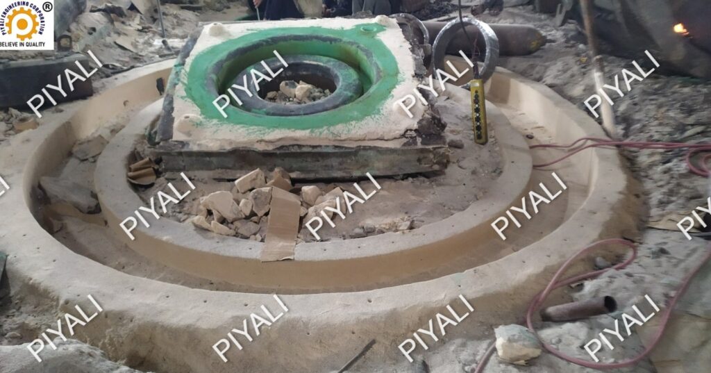
MOLDING
Molding is the procedure of pouring liquid into a specific mold to ensure it solidifies in a modified form. Sand and a binding substance packs around the pattern to make a mold. To form the shape of the finished product, the molten or liquid material pours into a mold cavity or hole.
MELTING AND POURING:
MELTING: The foundries typically use the melting and pouring process to cast metal parts such as gears. The metal usually melts in a furnace. After melting, the metal pours into the mold, which covers the empty space if needed.
The melting and pouring process is essential in gear production because it enables the creation of parts with complicated shapes and fine details. It also allows for the use of a wide variety of materials, such as iron, steel, and various alloys, to create gears with varying strengths and properties.
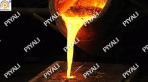
POURING: Pouring is the procedure of pouring molten metal into a mold to form a blank for a gear. For making the gear, the molten metal transfers into the mold from ladle.
The pouring process for gear manufacturing as follows:
Designing the mold is the first stage in the pouring process. This involves cleaning the mold to get rid of any dirt or debris that could degrade the final product’s quality. In a kiln or furnace, the metal melts to create the gear blank. The type of metal used will depend on the particular application and needs of the gear. The metal then pours into the mold after it has melted. It is important to ensure that the metal pours uniformly and the finished product is free from air bubbles and other flaws.
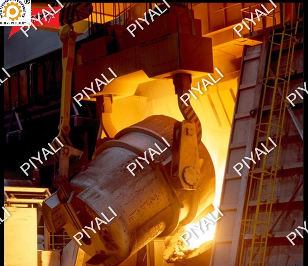
Steel Making & Ladle Analysis:
Steelmaking is the process of making steel from carbon, manganese, silicon, and iron ore that melt together in a kiln. Ladle analysis usually involves measuring the steel’s composition, including the amounts of carbon, manganese, silicon, and other elements. Using this information, it ensures that the steel has the power and durability required to function effectively in a gear.
The following steps involves in ladle analysis in gear manufacturing:
- Inspection: The first step is to physically check the ladle for any physical flaws, such as cracks or defects, using non-destructive testing techniques, such as visual examination or dye penetrant testing.
- Material identification: It is essential to understand the material composition of the ladle.
- Sampling: To perform a chemical analysis on the molten metal, it is essential to take out an accurate sample from the ladle. Using this information, it will be possible to determine whether the molten metal’s chemical composition is within the intended range.
- Chemical analysis identifies the chemical composition of the sample that it takes from the ladle. Various techniques such as spectroscopic techniques use for research purposes.
- Measurement of temperature: It’s essential to know how hot the liquid metal inside the ladle is.
- The degassing process involves releasing any gases that remain from the ladle of liquid metal.
STEP 3: Blanking
Blanking process in which a flat piece of metal is first cut into the rough form of a gear using a cutting tool, usually a die or punch. In the process of making gears, the blanking process is important as it sets the groundwork for the succeeding processes, including heat treating, finishing, and shaping. There are various techniques to complete the blanking process, including hobbing, broaching, shaping, and milling. These are:
- HOBBING: Gear hobbing is the process to cut the gear teeth into the blank with a special cutting tool called a hob.
- BROACHING: To make the gear teeth, broaching is the process of forcing an instrument with numerous teeth through the blank.
- SHAPING: Shaping is the process of giving shape to the gear teeth using a cutting instrument that moves in a circular motion.
- MILLING: By rotating a cutting instrument against the blank, milling removes material and shapes the blank into a gear.
HARD PUNCHING: Hard punching is the process of creating holes or marks in the gear teeth or other components of the gear using a high-force punching tool.
STEP 4: Heat treatment
Heat treatment is the process that enhances the hardness, strength, and durability of girth gear as well as its resistance. Heat treatment is a process that involves subjecting a girth gear to high temperatures, which results in a structural change in the material, and then cooling it down in a controlled way to improve its mechanical properties. The various heat treatments include carburizing, quenching and tempering, normalizing, and annealing. The type of heat treatment depends on the material composition of the edge and the desired mechanical properties.
HEAT TREATMENT PROCESS FOR KILN GIRTH GEAR AS FOLLOWINGS :
- Annealing: Annealing is a heat treatment process that can enhance the mechanical properties and performance of a material.The purpose of annealing is to reduce the hardness of the material while increasing its flexibility.
- Normalizing: Normalizing is a heat treatment process used on carbon and low-alloy steels. It can enhance the strength, durability, and machinability of the material, making it simpler to work with and less prone to cracks or other types of failure. By normalizing the material, any internal stresses that may have been introduced during earlier production procedures like casting or forging are removed.
- Quenching: An essential step in the heat treament process for girth gears is quenching. It involves quickly cooling the gear to the desired mechanical and microstructure properties after heating it to a specific temperature. The heated girth gear is quickly cooled to below its critical temperature during the quenching process, which results in the formation of a hardened microstructure.
- Tempering: As a crucial step in the heat-treating process for girth gears is tempering that involves reheating the hardened gear to a specific temperature below the austenitizing temperature while maintaining it there for a specified period of time.
- Carburizing: A typical heat treatment process called carburizing is used to increase the surface hardness of metal parts, including girth gears. During the carburizing process, the gear’s surface is exposed to a to carbon-rich atmosphere for a significant period of time. As a result, diffusion of carbon into the metal’s surface layer forms a harder, wear-resistant layer.
- Grinding: Grinding is a machining process that uses abrasive particles to remove a small amount of substance from the surface of the workpiece. Grinding is frequently used to improve the surface finish and dimensional precision of workpieces, as well as to remove surface imperfections that may have appeared during previous manufacturing processes.
INSPECTION : HEAT TREATMENT
Inspection is a crucial step in both heat treatments. It ensures that the material has acquired the desired characteristics and that the microstructure is free of flaws or abnormalities.
STEP 5: Gear Machining
Rough machining is the initial step of girth gear machining. The roughing process eliminates the excess material to make the gear blank ready for finishing.The final stage of gear production is gear finishing.
Finished Machining Process:
- Gear hobbing: The final step in the machining process is hobbing, which involves cutting the gear teeth into the blank with a special cutting tool at an exact angle and depth called a hob.
- Final inspection: Final inspection includes various techniques, such as eye inspection, ultrasonic testing, and magnetic particle inspection techniques to check the girth gear finishing.This guarantees that the gear is free from defects and fulfills the requirements for the application.
- Surface treatment: A surface treatment process applies to the surface of a material to making it more resistant to corrosion or wear. A surface treatment improves the girth gear’s wear resistance and longevity.
STEP 6: GEAR TESTING
Any defect in the girth gear can seriously harm the machinery and even force the manufacturing process to stop. Large rotating machinery like rotary kilns, ball mills, and cement mills require regular maintenance and care. Girth gear testing is an essential process in the maintenance and care of these equipment. Regular testing and inspection are necessary to guarantee the girth gear’s reliability and secure operation.
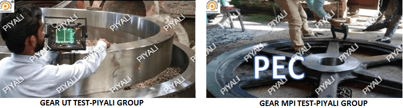
The various gear testing techniques are as follows:
- Ultrasonic testing: This non-destructive testing technique scans the girth gear with high-frequency sound waves to look for interior flaws.
- MPI Testing: A non-destructive testing method that detects surface and slightly subsurface defects in magnetic materials such as iron and cobalt.
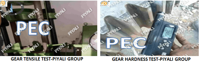
- Gear mechanical testing: This type of testing assesses the mechanical qualities of gears. These tests are essential for ensuring that gears operate correctly and securely in their applications.
- Hardness testing: Hardness testing determines the gear material’s hardness, which is a sign of its strength and durability. Brinell, Rockwell, as well as Vickers testing are common hardness testing techniques.
- Tensile testing: Tensile testing involves applying tension pressures to gear materials until they break in order to determine their strength and ductility.
- Dimension test: The dimension test is one of the critical measurements which includes checking various critical dimensions of the gear, such as tooth size, tooth profile, gear diameter, tooth thickness, and concentricity. These measurements ensure that the gear meets the necessary dimensional precision.
- Chemical test: Gear testing can use chemical analysis to figure out the properties and composition of the gear material. A spectroscope tests the elements that compose the gear materials or elements.
TEETH CUTTING PROCESS:
Teeth cutting is an essential process in gear production. It entails removing material from a gear blank in order to make the teeth on the gear. The process typically includes using a cutting tool to remove material from the gear blank in a particular pattern defined by the desired tooth shape.
TEETH CUTTING PROCESS:
- Hobbing: Gear hobbing is a machining process that uses a hob to cut teeth into a blank, resulting in the desired tool. The cutter and gear blank rotate at the same time to transfer the profile of the hob onto the gear blank. Gear hobbing includes master hob or index hob techniques on CNC gear hobbing machines that cut wheels, gears, pinions, worms, and shafts.
- Shaping: The common method of gear shaping involves the process to mount a gear blank in a shaper and using a tool that shapes it like the tooth that needs to be cut.
- Broaching: The process of “broaching” removes material from the gear blank until the desired tooth profile is obtained.
- Milling: In the milling process, the cutter moves axially along the length of the gear tooth at the appropriate depth to form the gear tooth.
DRILLING:
Drilling is a machining process used in gear manufacturing to make holes in gears or gear parts. There are various tools for drilling process, including twist drills, step drills, and pistol drills. The choice of tool depends on the size and shape of the hole. Drilling is an important process in the manufacturing of a gearbox, which helps to ensure the exact dimensions and functions necessary for the correct operation of the gearbox.
STEP 7: FINAL INSPECTION
Final inspection in gear manufacturing is a critical procedure to guarantee that manufactured gears meet the required specifications as well as quality.
DIMENSIONAL TEST:
Final machining dimensional testing is a quality assurance process used to make sure the finished item or component complies with the requirements for its intended use. The method of measuring the accuracy of the finished gear after it has been machined to its final dimension is known as dimensional testing. In the dimensional test, the diameter, the tooth profile and the tooth thickness are measured. These measurements are compared to the design specifications to identify if the gear meets the required specifications.
DP TEST:
A non-destructive testing (NDT) called dye penetrant inspection (DPI) is used to find surface-breaking defects in both metallic and non-metallic materials. Penetrant testing is cost-effective technique used for detecting surface flaws in machined parts. It is a common technique for girth gear inspection.
- Cleaning: The surface of the girth gear is completely cleaned with degreaser to remove dirt, oil and other impurities.
- Application of penetrant: The penetrant is then applied to the surface of the gear being tested. Any flaws or cracks in the material are penetrated by this penetrant.
- Dwell time: The dye remains on the surface for a certain period of time after penetrating any surface flaws or cracks. This dwell period enables the penetrant to completely penetrate any surface flaws and gives the surface time to drain off or remove any excess penetrant.
- Removing excess penetrant: Excess penetrant is removed by wiping it off the surface of the girth gear.
- Inspection: The girth gear’s surface is inspected for any apparent defects.
DP is a useful testing tool for detecting surface defects in girth gears and other components, and can help prevent failures and downtime in industrial applications.
VISUAL INSPECTION:
Visual inspection is an important quality control procedure that makes sure the gears are safe to use and satisfy the necessary requirements. This type of inspection allows detection of surface defects such as cracks, chips and pits that may have occurred during the machining process. and also help to identify other issues, such as improper tooth spacing or other dimensional errors, that may impact the performance of the gear. A number of techniques, such as, dye penetrant testing(DPI), visual examination under magnifying glass, and fluorescent inspection can be used perform visual inspection.
STEP 8: PACKAGING AND DELIVERY
MATERIAL DISPATCH PLANNING
Material dispatch planning is the process of making sure the right materials are available at the appropriate time and in the proper quantity to satisfy the production needs of the gear manufacturing.This involves identifying the materials necessary for each production phase, choosing the materials from the stock, and delivering them to the production unit.
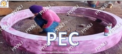
Anti-Rust Paint
Water proof packing:
In order to prevent water or other liquids from entering inside the gear mechanism and causing harm or corrosion, waterproof packing is essential.
Start by constructing a solid wooden box that is sufficiently big to hold the girth gear and have space for packaging materials.
Seal the container with a waterproof tape or adhesive to prevent water from entering the container.
To further guard against moisture, consider including a desiccant packet or moisture-absorbing substance, like silica gel.
Label the container clearly and concisely, including the recipient’s address, contact information and recipient’s name.
Wooden Box Packing:
A wooden box can be a good choice for packing heavy equipment for storage or transportation. To determine the proper size of the required wooden box, measure the girth gear first. Then choose a large, solid wooden box that can hold the equipment and leave the enough space for protection and security. The box needs to be strong enough to support the weight and pressure of the equipment. To prevent scratches and damage to the equipment during transportation, line the package with a layer of padding material like foam or bubble wrap.
Make sure to properly align the girth gear before carefully placing it inside the wooden box.
Seal the box carefully so that the contents do not shift or move.
It is important to include all the relevant shipping information on the box’s label, along with the proper handling directions.
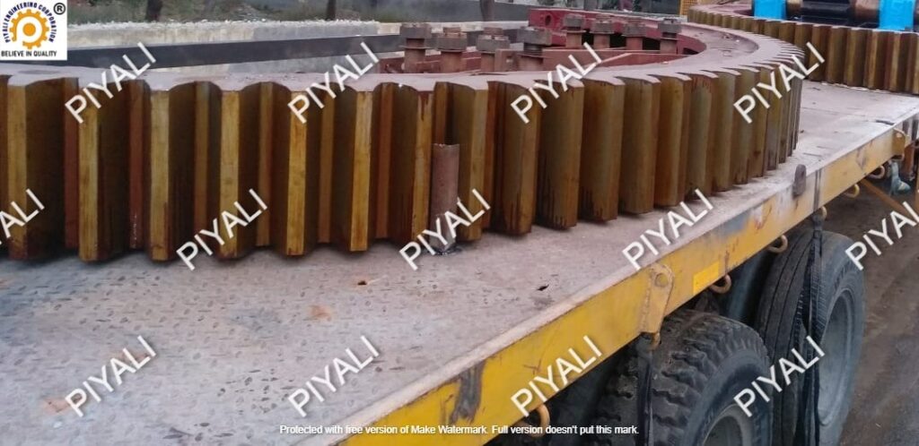
DELIVERY:
After completing the whole gear manufacturing process, the product is finally delivers to the customer.
KEY FEATURES:
- A 100 TPD kiln girth gear is typically large in size, and it must be capable of handling heavy loads and high temperatures.
- High-quality cast steel for 100 TPD kiln girth gears ensure its durability and strength.
- The design of the tooth shape of the 100 TPD girth gear ensures smooth and effective power transmission between the driving and driven components.
- Proper lubrication is necessary for kiln girth gear to ensure that it functions smoothly.
- Regular maintenance is necessary to detect wear or damage and prevent serious problems if they occur.
APPLICATIONS USED:
- Sponge Iron Plant
- Cement Plant
- Chemical Plant
- Carbon Plant
- Sugar and Paper Mills
- Fertilizer Plant
